ER Diagrams in DBMS
ER model in DBMS is the high-level data model. It stands for the Entity-relationship model and is used to represent a logical view of the system from a data perspective. In simple words, the entity relationship diagram is a blueprint that can used to create a database. E-R diagrams are used to model real-world objects like a person, a car, a company and the relation between these real-world objects.
Features of ER model
- E-R diagrams are used to represent E-R model in a database, which makes them easy to be converted into relations (tables).
- E-R diagrams provide the purpose of real-world modeling of objects which makes them intently useful.
- E-R diagrams require no technical knowledge and no hardware support.
- These diagrams are very easy to understand and easy to create even by a naive user.
- It gives a standard solution of visualizing the data logically.
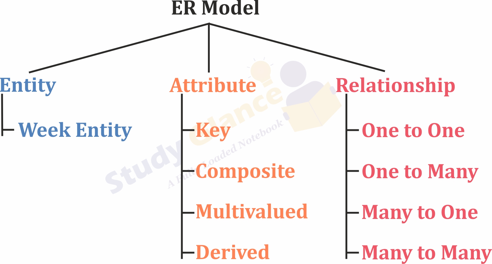
ER diagram basically having three components:
- Entities − It is a real-world thing which can be a person, place, or even a concept. For Example: Department, Admin, Courses, Teachers, Students, Building, etc are some of the entities of a School Management System.
- Attributes − An entity which contains a real-world property called an attribute. For Example: The entity employee has the property like employee id, salary, age, etc.
- Relationship − Relationship tells how two attributes are related. For Example: Employee works for a department.
| Component | Symbol |
|---|---|
| Entity |  |
| Weak Entity | 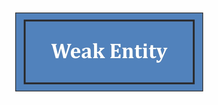 |
| Attribute | 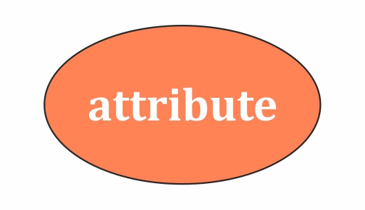 |
| Key Attribute | 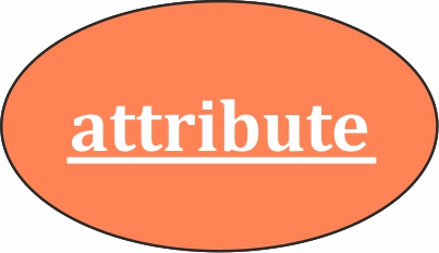 |
| Composite Attribute | 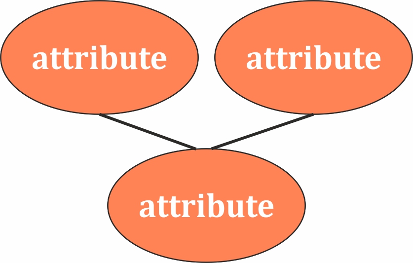 |
| Multivalued Attribute | 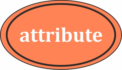 |
| Derived Attribute | 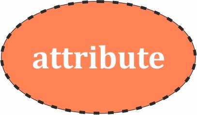 |
| Relationship | 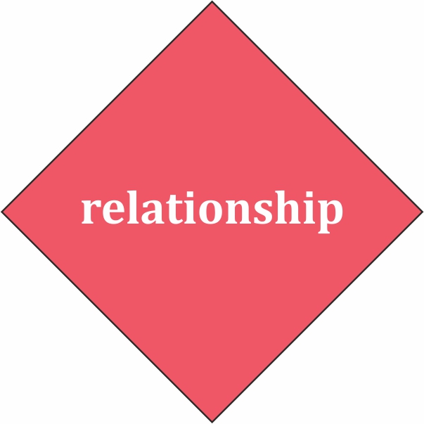 |
| Weak Relationship | 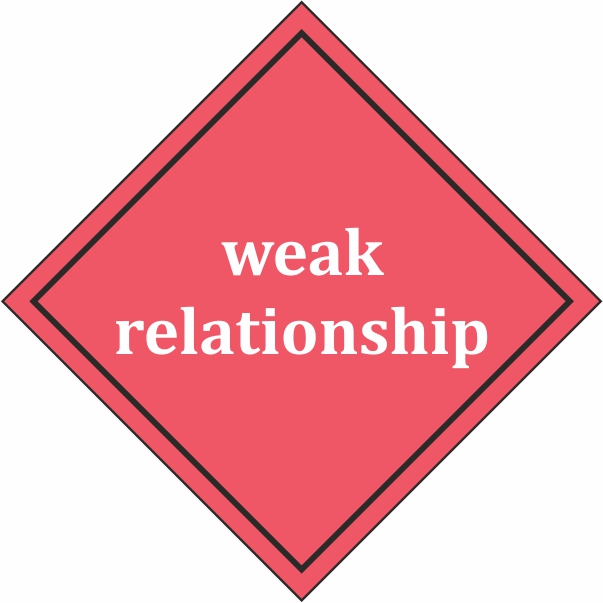 |
| Participation Constraints | 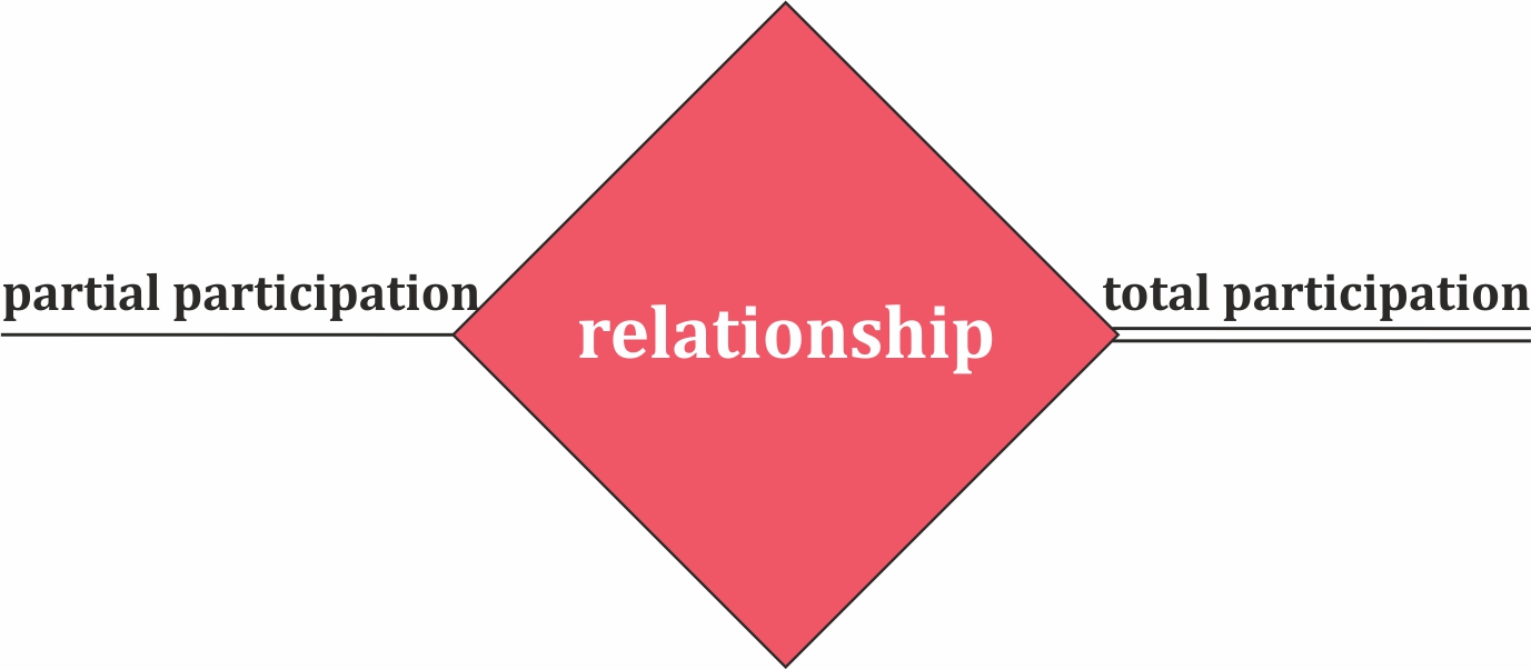 |
Next Topic :Attributes in DBMS